English|中文
This sample provides reference for you to learn the Ascend AI Software Stack and cannot be used for commercial purposes.
This sample applies to CANN 3.1.0 and later versions. The supported product is Atlas 200 DK.
Use Atlas 200 DK to run the YOLOv3 model, perform inference on the RGB data streams provided by binocular depth cameras, and detect the locations of objects in images in real time. Control the robotic arm's postures to make it move with the objects based on the depth data streams of the cameras.
| Material Type | Description |
|---|---|
| Inference platform | Atlas 200 DK |
| Binocular depth camera | RealSense D435 |
| Robotic arm | Dobot Magician |
| Main control platform | Ubuntu18.04 LTS-x64-Huawei Matebook X Pro |
| Router | Huawei 4G wireless router B311 |
| Object to be detected | Ascend icon |
- Deploy the development environment. For details, see the Atlas 200 DK documentation.
- Deploy the operating environment. For details, see the Atlas 200 DK documentation.
- Check whether the inference platform is successfully set up. See the Ascend sample YOLOV3_coco_detection_picture.
- Install the SDK by following the RealSense SDK 2.0 Build Guide.
- Check whether the SDK is successfully installed. See opencv_viewer_example.
-
Download the Dobot Magician Python API. See pydobot.
-
Add the move_by_angle API.
Edit the pydobot/dobot.py file and add the move_by_angle function definition code after the move_to function.
def move_by_angle(self, j1, j2, j3, j4, wait=False):
    self._set_ptp_cmd(j1, j2, j3, j4, mode=PTPMode.MOVL_ANGLE, wait=wait)
-
Install the API.
python3.7.5 setup.py build
python3.7.5 setup.py install
-
Check whether the API is successfully installed. See Python Example in the Python API description document.
NOTE
- The official Python API of Dobot Magician does not provide the angle control mode. Therefore, you need to manually add the move_by_angle mode.

- The following figure shows the data flow of the robotic arm following the path of object movement. The Atlas 200 DK inference platform (operating environment) interacts with the Ubuntu main control platform (development environment) through a router. The Atlas 200 DK is responsible for inference of the YOLOv3 object detection model. The Ubuntu main control platform sends the RGB data of Intel RealSense to the Atlas 200 DK through the router, receives the inference result from the Atlas 200 DK, and controls the robotic arm based on the inference result.

-
Problem analysis
-
Analysis 1: Movement mode of the robotic arm
The J1, J2, and J3 axes of the robotic arm are driven by independent motors and move independently. The J1 axis controls the movement of the end center on the xy-plane. If the polar coordinate mode is used for analysis, it can be known that the J1 axis motion affects only the angle of the end center on the xy-plane and controls the camera to face the object. The J2 and J3 axes are used to control the movement of the end center on the xz-plane, control the camera to align with the object in height, and keep a proper distance between the camera and the object.
-
Analysis 2: Camera location, posture, intrinsic parameters, and extrinsic parameters
According to the schematic diagram of the system, the binocular camera is installed at an end center of the robotic arm, and the location and posture of the end center are the location and posture of the binocular camera. The location of the end center may be directly obtained by using the robotic arm SDK, and may be represented as
$(T_x, T_y, T_z)$ . According to observation, when the robotic arm moves, the camera does not rotate around the X or Y axis, and only rotates around the Z axis. The angle of rotation around the Z axis is a motion angle of the robotic arm's J1 axis. Therefore, the camera posture may be represented as$(0, 0, J_1)$ . The extrinsic parameter matrix of the camera can be calculated according to the proceeding analysis. The intrinsic parameter matrix of the camera can be directly obtained through the API of RealSense. -
Analysis 3: Task description
A task in which a robotic arm moves in space with an object may be expressed as two subtasks:
- The movement of the robotic arm always makes the camera aim at the object, that is, the object is located in the center of the field of view (image) of the camera.
- When the distance between the object and the camera is greater than the standard distance, the robotic arm controls the camera to move forward, and vice versa. That is, the camera always keeps a certain distance from the object.
The movement of the robotic arm may be implemented by controlling angles of the three axes, that is, the degrees that the J1, J2, and J3 axes need to move respectively after the location and depth data of the object in the image coordinate system are obtained, so that the object after movement is located in the center of the field of view of the camera and has a proper distance.
-
-
Mathematical model establishment
-
Coordinate system conversion: image coordinate system -> camera coordinate system -> world coordinate system
-
Intrinsic parameters of the camera
The intrinsic parameter matrix of the camera can be directly obtained through the API of RealSense. For details, see the API reference document. If camera lens distortion is not considered, the intrinsic parameter matrix
$K$ may be represented in the following format:$$ K = \begin{bmatrix}f_x & 0 & c_x \\ 0 & f_y & c_y \\ 0 & 0 & 1 \end{bmatrix} $$
-
Extrinsic parameters of the camera
According to the preceding calculation of the camera location, the translation vector
$T$ may be obtained:$$ T = \begin{bmatrix} T_x \\ T_y \\ T_z \end{bmatrix} $$
According to the foregoing calculation of the camera posture, a rotation matrix
$R$ of the camera may be obtained:$$ R = \begin{bmatrix} 1 & 0 & 0 \\ 0 & \cos\theta_0 & -\sin\theta_0 \\ 0 & \sin\theta_0& \cos\theta_0 \end{bmatrix} \cdot \begin{bmatrix} \cos\theta_1 & 0 & \sin\theta_1 \\ 0 & 1 & 0 \\ -\sin\theta_1 & 0 & \cos\theta_1\end{bmatrix} \cdot \begin{bmatrix} \cos\theta_2 & -\sin\theta_2 & 0 \\ \sin\theta_2& \cos\theta_2 & 0 \\ 0 & 0 & 1\end{bmatrix} $$
Therefore, the camera coordinate system can be converted to the world coordinate system as follows:
$$ \begin{bmatrix} x_w \\ y_w \\ z_w \end{bmatrix} = R \cdot \begin{bmatrix} x_c \\ y_c \\ z_c \end{bmatrix} + T $$
-
Conversion from the image coordinate system to the world coordinate system
Complete conversion process from the image coordinate system to the world coordinate system:
$$\begin{bmatrix} x_w \\ y_w \\ z_w \end{bmatrix} = R \cdot K \cdot \begin{bmatrix} x_p \\ y_p \\ 1 \end{bmatrix} + T$$
-
-
Motion logic of the J1 axis
According to the preceding assumption, the motion problem of the J1 axis can be analyzed in the XOY projection plane of the world coordinate system.
As shown in the figure, A(
$x_A$ ,$y_A$ ) is the actual location of the object, and B($x_B$ ,$y_B$ ) is the center of the current camera's field of view (image center). To ensure that the object is located in the center of the field of view after the robotic arm moves, the moving angle$\theta_1$ of the J1 axis may be expressed as:$$ \theta_1 = \arccos[\frac{\overrightarrow {OA} \cdot \overrightarrow {OB}} {\mid\overrightarrow {OA}\mid \cdot \mid\overrightarrow {OB}\mid}] $$
That is:
$$ \theta_1 = \arccos(\frac {x_A x_B + y_A y_B} {\sqrt{x_A^2 + y_A^2}\sqrt{x_B^2 + y_B^2}}) $$
-
Motion logic of the J2 and J3 axes
Create equations about
$\theta_2$ and$\theta_3$ :$$l_2\cos(\alpha_2 + \theta_2) + l_3\cos(\alpha_3 + \theta_3) = \Delta x + l_2\cos(\alpha_2) + l_3\cos(\alpha_3)$$ $$l_2\sin(\alpha_2 + \theta_2) + l_3\sin(\alpha_3 + \theta_3) = \Delta z + l_2\sin(\alpha_2) + l_3\sin(\alpha_3)$$ Solve the equations:
$$\theta_3 = \arctan(\frac {R_z} {R_x}) - \arccos(\frac {l_3^2 - l_2^2 + R_x^2 + R_z^2} {2l_3\sqrt{R_x^2 + R_z^2}}) - \alpha_3$$ $$\theta_2 = \arccos[\frac{\Delta x + l_2\cos\alpha_2 +l_3\cos\alpha_3 - l_3cos(\alpha_3 + \theta_3)}{l_2}] - \alpha_2$$ Where,
$$R_x = \Delta x + l_2\cos(\alpha_2) + l_3\cos(\alpha_3)$$ $$R_z = \Delta z + l_2\sin(\alpha_2) + l_3\sin(\alpha_3)$$
-


-
Obtain the source package.
On the Ubuntu main control platform, run the following commands as a non-root user to download the source code repository:
cd $HOME
git clone https://github.com/Ascend/samples.git
-
Obtain the network model required by the sample.
Obtain the model used in the sample by referring to the following table and save it to the project directory of a common user in the development environment.
cd $HOME/samples/python/level3_multi_model/Robotic_Arm_Object_Following/model
Model Name Model Description Download Link yolov3_ascend_logo Ascend icon detection model based on TensorFlow-YOLOv3 Download the model and weight files by referring to the links in README.md in the https://github.com/Ascend/ModelZoo-TensorFlow/tree/master/TensorFlow/contrib/cv/yolov3_darknet53/ATC_yolov3_darknet53_tf_xdzhangtongxue directory of the ModelZoo repository. - The OM model has been provided in ModelZoo and can be directly used.
-
Run the following commands to upload the samples directory of the main control platform to the inference platform, for example, /home/HwHiAiUser, and log in to the Atlas 200 DK inference platform as the HwHiAiUser user (running user):
scp -r $HOME/samples/ HwHiAiUser@xxx.xxx.xxx.xxx:/home/HwHiAiUser ssh HwHiAiUser@xxx.xxx.xxx.xxx- xxx.xxx.xxx.xxx indicates the IP address of Atlas 200 DK. When Atlas 200 DK is connected to the Ubuntu main control platform over the USB port, the IP address is 192.168.1.2.
-
Run the executable file on the Atlas 200 DK inference platform. The program waits for the RGB data from the RealSense for inference.
cd $HOME/samples/python/level3_multi_model/Robotic_Arm_Object_Following/src
python3.6 object_detection.py
-
Run the executable program on the Ubuntu main control platform, send RGB data to Atlas 200 DK, and receive the inference result to control the Dobot Magician robotic arm.
cd $HOME/samples/python/level3_multi_model/Robotic_Arm_Object_Following/src
python3.6 robotic_arm_object_following.py
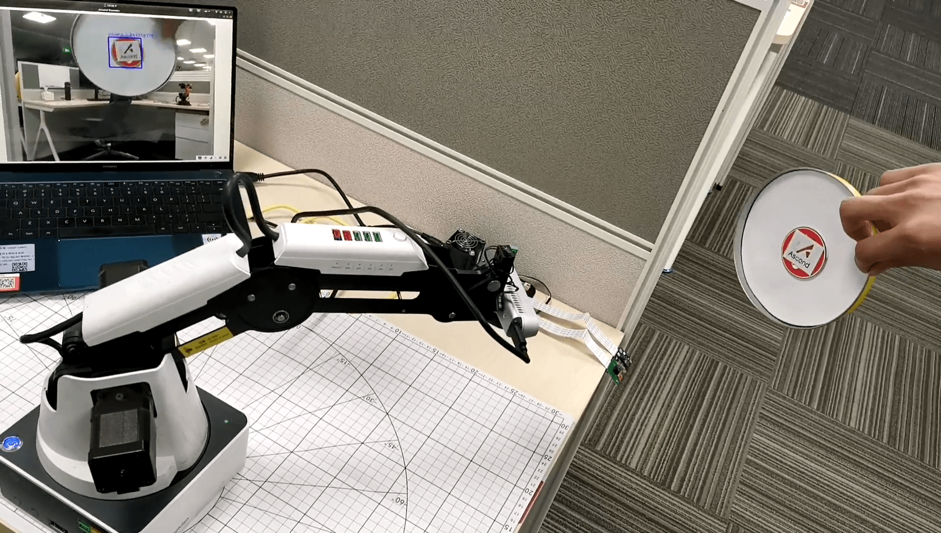
After the running is successful, you can use the Ascend icon to control the movement of the robotic arm. The expected effect is as follows:
